Zaph|Audio - SB Acoustics 2-Way : Box Plans
Box Plans
There are no elaborate box plan shown here, only a basic one. The volume of the box used matches the volume of a Parts Express 0.75 ft³ rectangular box so that those who may not have box-making ability would have this option. This box plan includes a single brace as does that of Parts Express, but the brace is positioned differently. I have never liked vertical side braces due to possible reflections in the midrange. The horizontal shelf brace used in these plans braces the front and rear baffles as well as the long sides. This should provide some additional benefit, but by no means is that guaranteed.
Sketchup is a great tool for creating drawings. I used it for this design for the first time and am amazed at what it does as a free product. All of the drawings below were created with it.

Photos and Construction
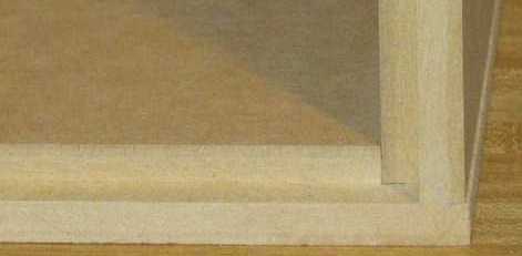
There is certainly more than one way to construct a box. When using Medium Density Fiberboard (mdf), a plain butt-joint is actually a fairly good one when glued well. As you can see in the picture below, the sides and back baffle are all cut from one length of mdf. The sides have been routed to match the dimensions of a Parts Express 0.75 ft³ front baffle that can be purchased separately if desired. That was the option I took, so that the measurements included the roundover of the Parts Express baffle. It was also easier.
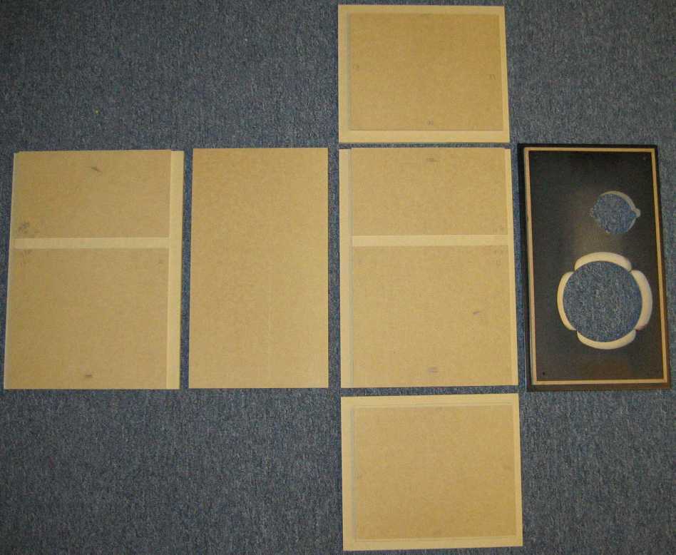
Notice that the back side of the woofer cutout has been opened for better air flow. You can use a straight chamfer or, as shown in the picture, a cove bit. The cove bit provides a little more of an opening for the same bit size. The edges and the shelf brace slot were cut with a table router. This makes for a very precise cut and a tight seal once glued together.
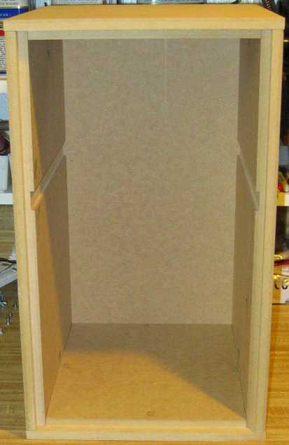
The basic box assembled without the brace was used during initial testing with an accelerometer. I'd planned to show how the before/after of bracing affects the box side resonances, but made a mistake by leaving the microphone calibration file in play when making the measurements without the brace. This was more out of curiosity rather than as an attempt to prove the effectiveness of bracing.
You may also have noticed that the brace isn't shown at all. I've left that out because even I find it easier to measure for it after test fitting the box. I'm leaving that part to you.
 |
 |
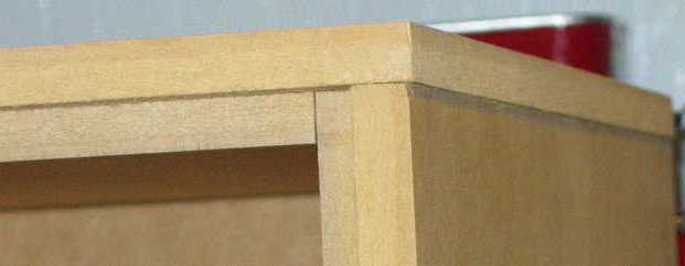
I have not yet veneered the boxes so you'll just have to put up with looking at plain old mdf pictures for now. In fact, I'll bet that you didn't even realize that all pictures above were taken before gluing anything at all! If you look closely you'll see that there's no evidenc of glue at any of the joints. Routed edges with good square-cut sides lets the box stand on its own when pieced together to check for proper dimensions of the cuts.
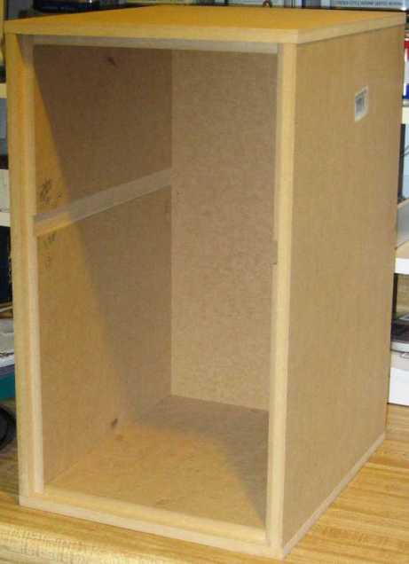
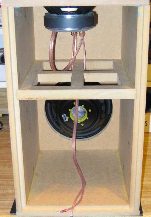
Here's a picture with the brace installed, the box side panels glued and the passive radiator installed. Don't be confused by the driver at the top. I set the front baffle on the top of the box to take the picture. It is just a straight-forward, typical box, but the whole point of this project was to keep it simple and see how much bang-for-the-buck one could extract from a set of drivers such as these.
David L. Ralph © 2009