Zaph|Audio - SB Acoustics 2-Way : In-Box Measurements
In-Box Measurements
We must have a good set of accurate sound pressure and impedance measurements to design. This has to be done on the baffle due to the diffraction that is inherently a part of the results and since it's inherently dependent on the dispersion of the driver at 90 degrees off-axis. We'll include an examination of the choice made for the layout and see how that plays out in the raw measurements.
SPL Measurements
After having measured the drivers on a large baffle and modified the tweeter, we now need to measure them in the box, both SPL and impedance. Some software can take the raw free-air impedance and incorporate the box T/S parameters to calculate the in-box impedance. This is very useful in examining options prior to box construction. Since we have a box constructed, we'll use the actual in-box measurements, both closed box and with the passive radiator.
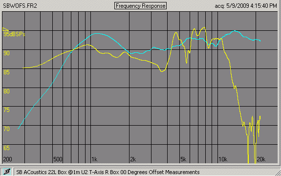
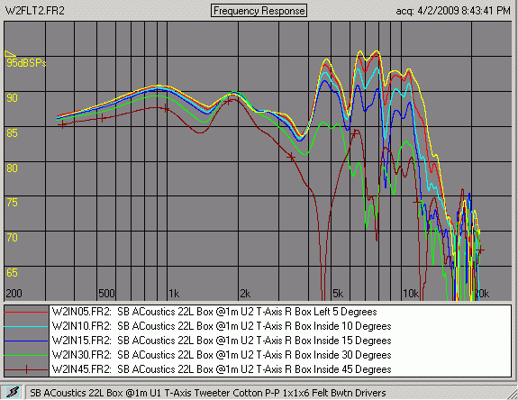
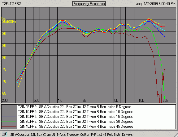
Let's start with the in-box quasi-anechoic SPL responses. This does not include the box impact because of the time limit required for the impulse windowing. The tweeter response is complete, however. Note that the upper limit is just under 24K due to the sample rate of the sound card used with the measurement system, Liberty Audiosuite (LAUD) from Liberty Instruments. The files have been processed for display in its successor, called Praxis.
All of the measurements presented throughout these pages have no smoothing applied. This allows everything to be seen, warts and all, even though our hearing tends to "smooth" the result. We don't necessarily hear all of the small peaks/dips seen, especially those that are very narrow.
Impedance Measurements
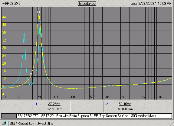
The tweeter impedance measurement may be made at any time. The woofer should be measured in the box since T/S parameters may vary from spec a bit and especially for a reflex design, since the latter is more sensitive to T/S variances than is a closed box. Even more so for a passive radiator, since it has its own set of T/S parameters. In addition, a certain amount of breakin should be made because T/S parameters can change a bit, primarily due to mechanical suspension compliance shift.
I ran a medium level 30Hz signal through the woofer with the passive radiator in place for about 3 hours immediately prior to making the last measurements. It was sufficient to make it appear that my eyes were blurring. The closed box measurement did not include a breakin period. The final measurements are shown below with markers placed roughly at the tuning frequency for each one.
Importing Measurements into Software
This can be a make-or-break task. I say that because some aspects are not always obvious. It's possible to simply import the raw data files into design software (those that have that function) and design the crossover from that data only. I've done this at times with some success. I'm often not inclined to create a more complete model, since at times it is sufficient to use direct measurements only so that the crossover can be implemented within CAD software that also has digital filter emulation. You can create any kind of crossover, passive or active, then audition it without ever having to construct a physical crossover. The benefit is enormous.
Another option is to import the measurements, then create a minimum-phase model within the software. This can provide more flexibility because the response at points other than the measurement point may then be predicted. Some software allows optimization using several points simultaneously. We'll be taking advantage of that during the crossover design.
Creating the Woofer Model
A midwoofer is often a difficult part for DIY because the highpass, to include the baffle step, cannot be measured directly with complete accuracy in most rooms. There are some workarounds, but each one has its inaccuracies. The method we'll examine here gave reasonable results and may be a bit more accurate than some other methods, though it's not been verified.
When creating this model I intially took a different approach that seemed to have worked a bit better. This involves several steps that uses some freely available software. In the end it resulted in more of a confirmation of the T/S extension method, but the alternate, non-T/S procedure should work with most optimization software, free or otherwise. It requires close-mic measurement coupled with extra post-prosessing. The page on 2-pi to 4-pi shows some examples of how you can use certain measurements to create this woofer model.
David L. Ralph © 2009